

Introduction:
The purpose of this thread is to explain in detailed layman's terms the steps involved to make a simple LED light. You don't have to be an electrical engineer to make one of these lights. With a little effort, practice and some basic knowledge of electricity anyone can make an LED light fixture. This project is a good way for anyone with some reservations or hesitation about pulling the trigger on a large LED project to get their feet wet on something small so that they can get the basics down before diving into something major. I am by no means an expert on electricity and this is only my second time soldering anything. I'm planning on doing a large scale fixture for my 75 gallon in the future.
Step 1: Gathering supplies
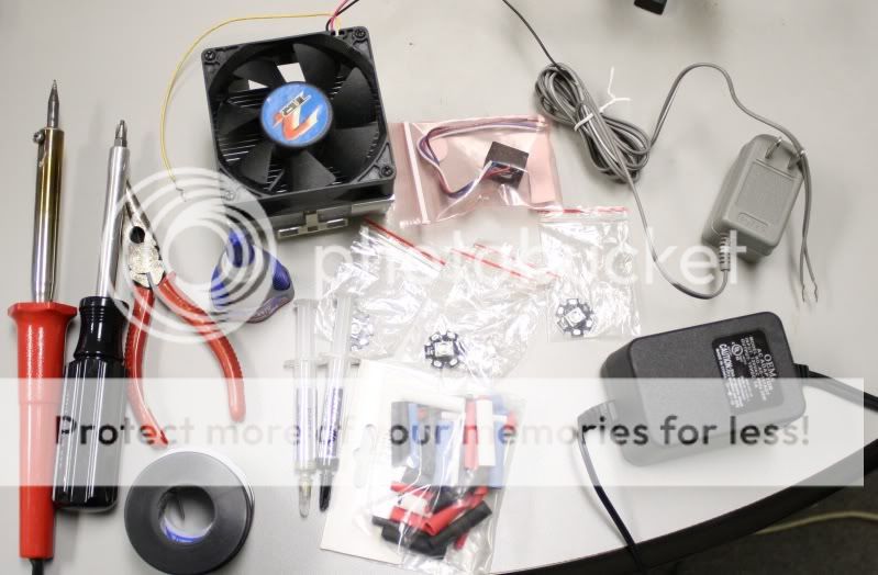
Tools -
Soldering iron ? get a good one from weller, I did not do this and I am paying for it now! This one I am using is terrible.
Sponge
needle nose pliers
toothpicks or paperclips
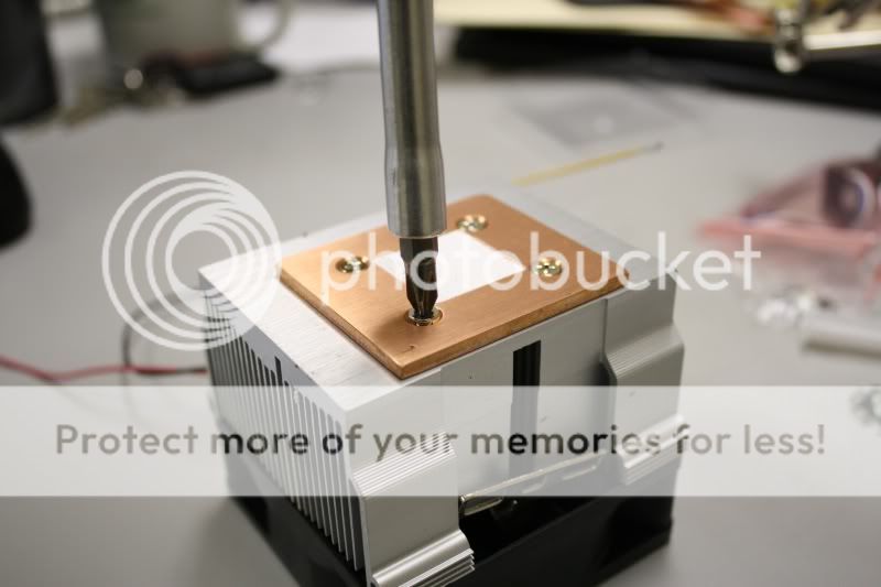
screwdriver ? I needed this, you may or may not
heat gun or hair dryer (cigarette lighter will work in a pinch)
Materials -
First a little background on how LEDS are typically configured for an aquarium as this will help you to understand how to pick your materials. Most people are using a DC power supply of some kind and connecting a number of drivers to that and then connecting strings of LED's in series which means connecting the negative of one to the positive of the next in a 'string'. The amperage of the power supply will tell you how many strings you can run and the voltage will tell you how many LED's it can power on each string. I suggest you click the links in the below sections to gain a better idea of what I am explaining as they are mostly to data sheets which are important and you will be referring to them when planning to do a larger project.
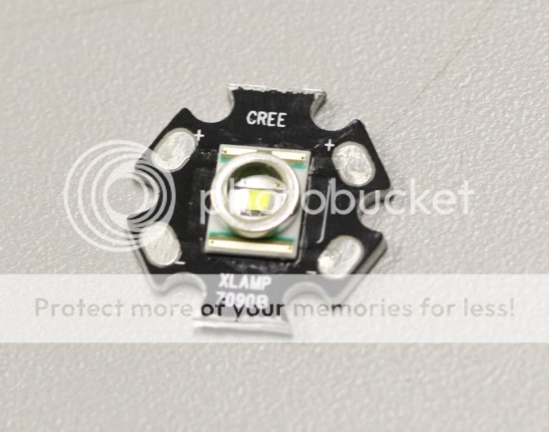
LED ? The LEDS you choose will be based on your project. I chose 4 white Cree XPE from dealextreme for mine as I wont be needing blue because this will be a fuge light. The data sheets for these LED's can be found at Cree's website. Choose Your LED's carefully as they are not all extremely bright like these. Look for the correct bin. You'll want the 'luminous or radiant flux group' section of the bin to say Q4 or Q5 for white. The royal blue color is great for actinic and makes coral color pop. You'll want your LED's to come pre-mounted because when they are unmounted they are very small and impossibly hard to solder for a novice. Here are some good websites to buy the kind of LED's and supplies we will be needing.
http://www.ledsupply.com/
http://www.dealextreme.com/
http://www.cutter.com.au/
Driver ? You need a constant current driver to run these LEDs. I don't want to get into all the reasons why you need this, just know that if you try to not use a driver your LEDS will not last very long. For this project I chose to use a regular non-dimming 1A Luxeon buckpuck from ledsupply. There are for clearly labeled wires coming out of it, two (+ and -) connect to the power supply and two (+ and -) connect to the LED string.
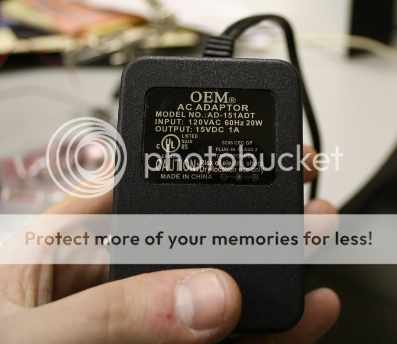
Power Supply ? For this small project look for one of those big black square plugs that most all of your electronics uses. I chose one that was for a cable modem. Look at the label of your power supply. The amperage will tell you how many strings of LED you can run from it and the voltage will tell you how many LEDs it can power on each string. Just add up the voltage of all the LED's which run at 3.7V each. Since my buckpuck is 1A and must have an input voltage between 5-32 V my 1A 15V DC power source should work fine for 1 string of LED running at 1A and since the forward voltage of each LED is 3.7V I can power a max of 4 LEDs on the string because the fifth would put me over 15V. For larger projects, get bigger power supplies (like for computers) which generally can do 24V and more amps lets say for example 8A, which would allow you to run 8 strings at 1A and 6 LED per string for a total of 48 LED .
Heat sink ? You will be needing a heat sink of some kind. This is what you mount the LED's to. These kinds of LED get very hot and can damage themselves if they get too hot. Copper or aluminum work great for this. A small piece of aluminum will work fine (can be found at home depot). I chose a processor heatsink and fan because I already had it in a pile of computer junk. For a project this small it really doesn't matter what you choose so long as there is something there dissipating the heat. For larger projects, the heatsink becomes much more crucial. You should also give some thought to how you will be mounting the heat sink over the tank and possibly how you will be shielding it from saltwater. These concepts are not covered in this tutorial.
Other materials -
Arctic silver thermal epoxy ? I chose to use this as it is the easiest method of mounting the LED's while and is made for heat transferring situations like this.
60/40 rosin core solder ? the appropriate solder for the job
22awg solid copper wire ? thin and easy to work with. Any thin wire works though, I used speaker wire on my first led project.
Heat-shrink tubing ? for insulating wire connections
Step 2: Mounting the LED's and driver
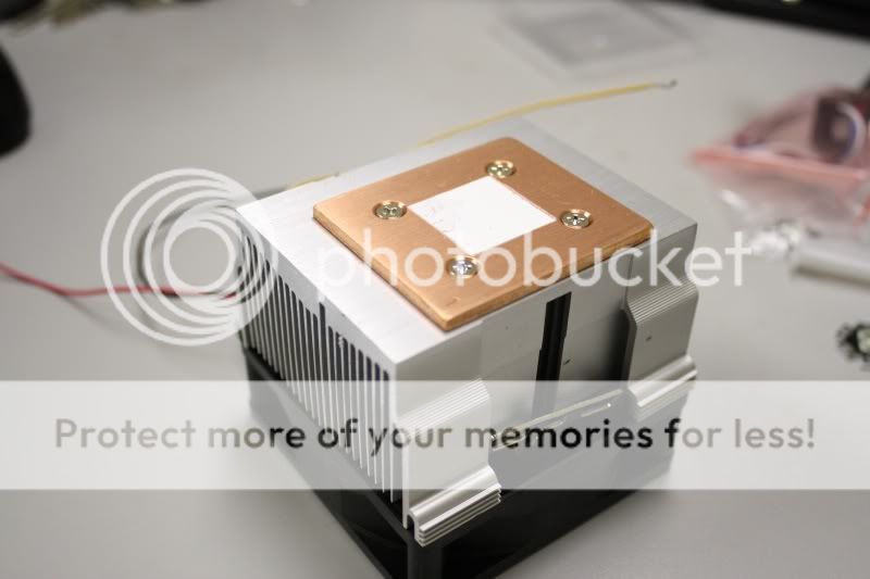
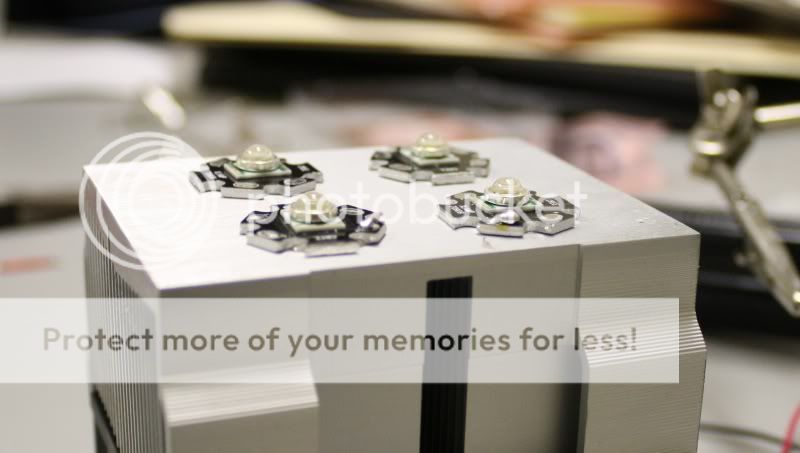
First make sure your heat sink is clean and has ample space to mount your LEDs. Mine had this copper bar on the bottom and under it was a bunch of thermal paste that I had to clean off with some tissue paper.
Decide how you want to arrange the LED's. Take note of where the + and ? soldering pads are on the stars because we will be soldering small bits of wire to these to connect the LED's in a string.
There are usually two +'s and two -'s on each star. Either will work fine and you will not use all the pads.
Take into account that you will be connecting the positive lead from the driver to the positive on the first LED. Then you connect the negative from that first LED to the positive of the next one and so on until they are all connected with the negative of the last LED connected to the negative lead from the driver so to make it easy, try to make the pads line up.
Pick an out-of-the-way spot for your driver such as the back or side of your heat sink. These heat up a bit as well so you can use the thermal epoxy to glue it. Just make sure the wires can reach what you have chosen as your first and last LED. Superglue does not work.
Take your time with this step and plan out what you are connecting and where. You want the pads to be close but don't put them so close that it is difficult to bridge the connections with a small bit of wire.
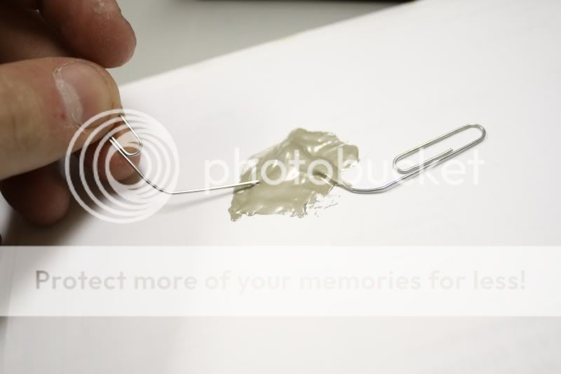
The Arctic silver thermal epoxy is a two part epoxy. Mix up equal parts of it on a paper plate or some paper using the toothpicks or paper clips. You'll only need a tiny glob of each. I made one of my gobs too big and then had to add more of the other part and ended up with a lot of waste.
After mixing, put a small amount where you want the LED to attach and press down a little. You only need a tiny amount of epoxy to attach them. I actually tried to remove one and that was definitely a no-go. This stuff is very strong so take your time and make sure you do it right the first time.
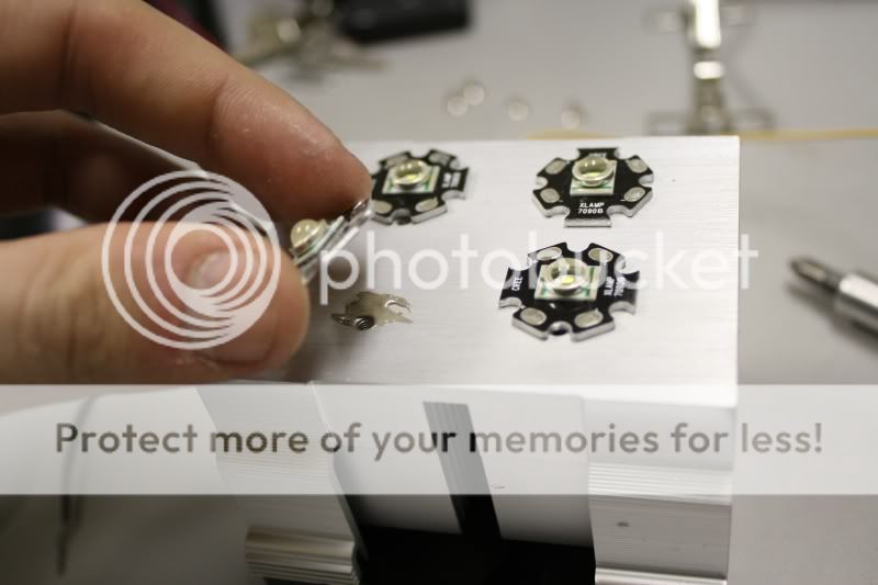
Attach all the LED's and drivers this way to your heat sink of choice. Let the glue set for about 5 minutes before soldering to the stars.
Step 3: Preparing the wires
Steps 3 and 4 are going to be repeated until you have the entire string connected. Do step 3 (Measure, strip, tin) then step 4 for each connection you have to make. Do not cut all the wires and then tin and connect them because you will confuse yourself, just do one connection at a time.
Plug your soldering iron in so that it starts heating up we will be using it for the next few steps. Also, wet the sponge (not sopping wet, just dampen it) we will be needing that as well.
Measure the wire and cut it. Do not use more wire than you need. It is best to make the wires as short as possible.
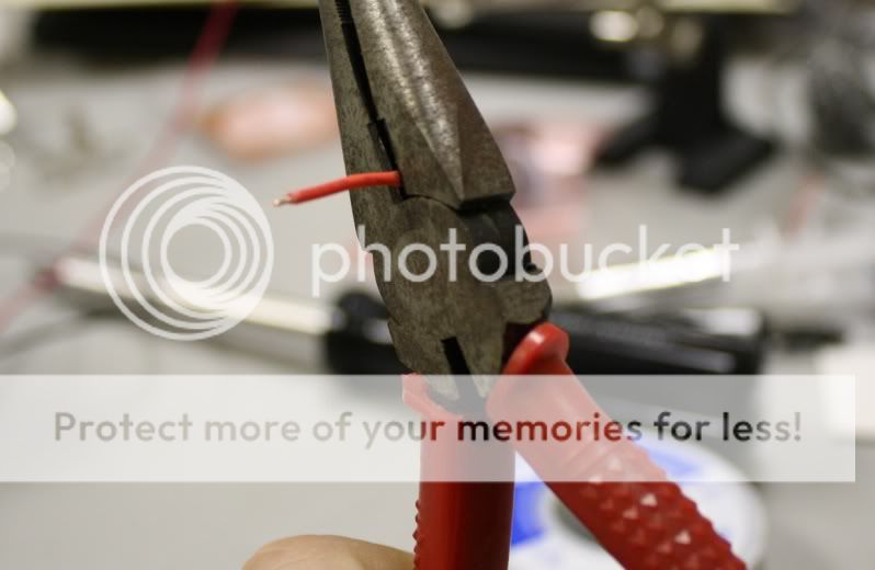
Strip off some of the insulation. Do not strip off more than you need to. You see these tiny little pads on the LED stars? You will only need bare wire of about the width of one of those pads. Use your dykes or needle nose pliers to accomplish this. Just squeeze the cutting blades of your tool down a bit and release repeatedly while rotating the piece of the wire. This will score the insulation which you should be able to tear off with your thumbnail.
Disclaimer: I am an extreme novice at soldering and barely have the skills to do this project. I know there are ways to get the solder much much neater but that is not our goal here. This tutorial is written by someone who knows only the basics of soldering and for people with no experience doing it. Also, THE SOLDERING IRON IS VERY HOT DO NOT TOUCH IT OR PUT IT DOWN ON ANYTHING THAT CAN BURN BECAUSE IT WILL BURN IT!!!:lol:
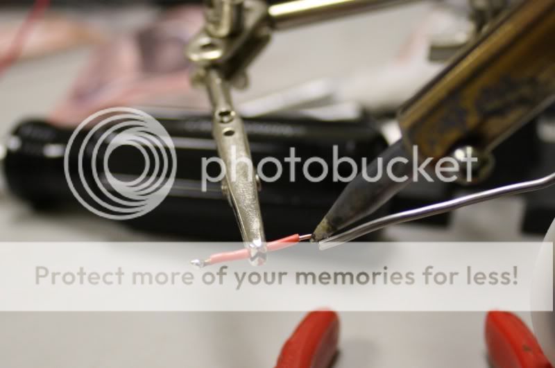
Now, we will be 'tinning' the wires which is basically just getting some solder on the bare tips we've made. This is how I did it, look here to find the correct way. To do this pick up your (hopefully hot by now) soldering iron and touch the solder to it. You will see the solder melt instantly and appear to become part of the tip, its not. Quickly rub the tip on you sponge and you should see the solder get shiny and start to look something like the T-1000 from terminator 2 (liquid metal). Then apply this to the tip of the wire by touching it to the bare end of the wire. MAKE SURE YOU HOLD THE WIRE WITH THE TWEEZERS OR NEEDLE NOSE PLIERS BECAUSE THE IRON IS INCREDIBLY HOT. You should only need a tiny bit of solder on the tip of the wire, just enough to turn the exposed copper silver in color, if you get more than you need on the tip, no big deal. Touch the iron to it briefly and some should stick to the iron. I'm sorry i don't have better pictures of this but I don't feel comfortable handling the camera and the soldering iron at the same time so this one will have to do.
Step 4: Making the connections
Now we will be connecting the LED's. First get some solder on your iron like we did for tinning the wires (apply solder and wipe on sponge). Then touch the iron with solder onto one of the pads so that you get a little gob of solder on it. Do this again for the other pad you are connecting with.
Pick up your tinned wire from last step with tweezers or needle nose pliers. Hold the wire in place with the ends touching the two pads that you are connecting (with the pre-applied gobs of solder) and touch the iron to it. Be careful not to touch the iron to the LED itself because that will ruin it. You should only need to keep the iron there for a split second to melt the solder. You can then release the wire and make the other connection the same way, just briefly touch the iron to the solder and the tinned wire to connect them.
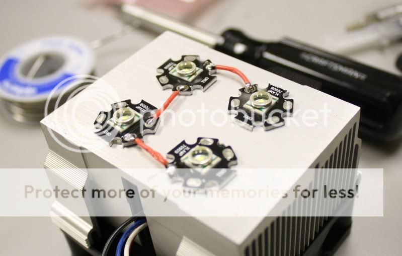
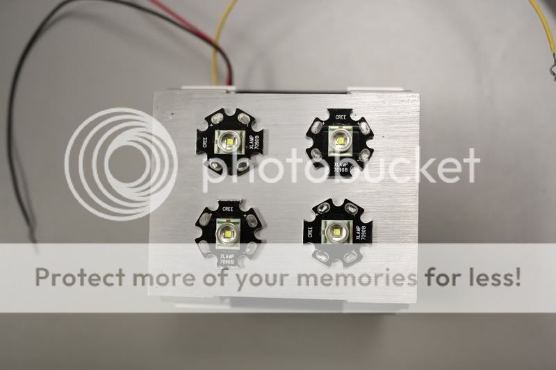
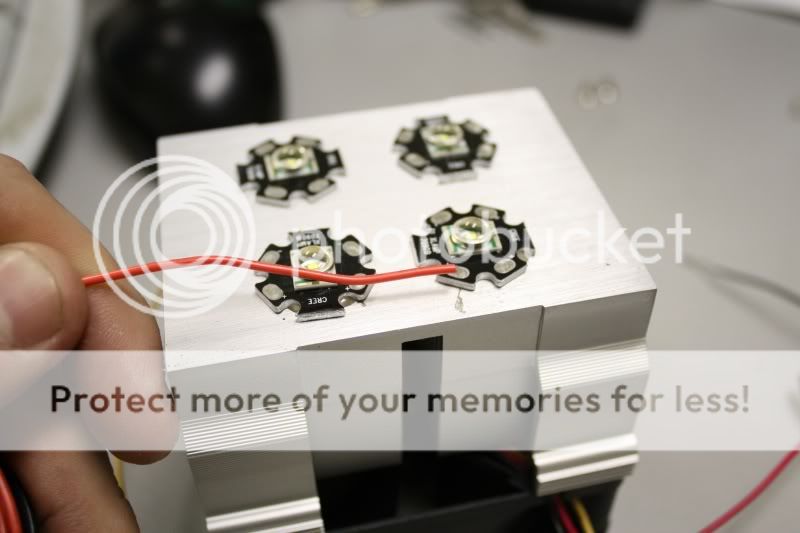
That wasn't so hard, was it? Now repeat steps 3 and 4 until you have connected all the LED's, negative to positive, unlike the above picture. can you spot the error? :tub:
Tin the ends of LED leads from the driver and connect the positive lead to the positive of your first LED and negative to the negative of your last LED.
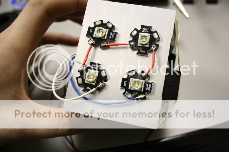
I figured out during the next step that I had made some connections wrong.:iamwithst
Step 5: preparing and connecting the power supply
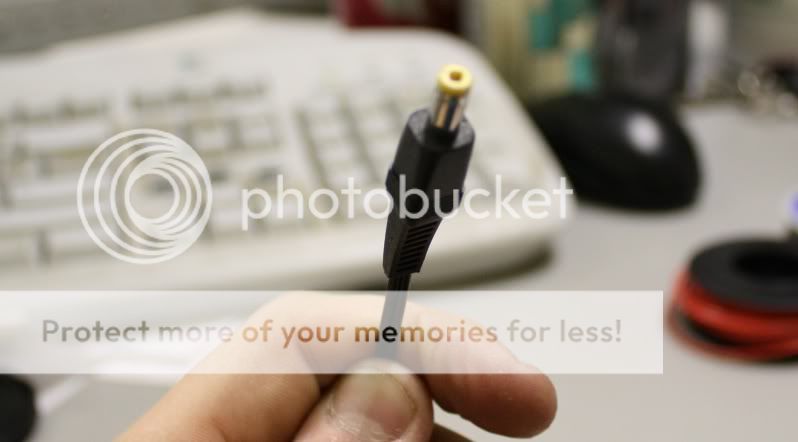
Your power supply probably has one of these round proprietary connectors on the end of the wire that connects to whatever it was meat for. Just go ahead and cut that connector right off.
Divide the wire down the center and strip about ? to ? of an inch of the insulation off just like we did before. Be careful though, the wires are probably stranded, which means instead of a a single wire inside the insulation, there will be a number of thinner wires inside there. This is to make the wire more flexible. After stripping the insulation off, twist the bare wire together.
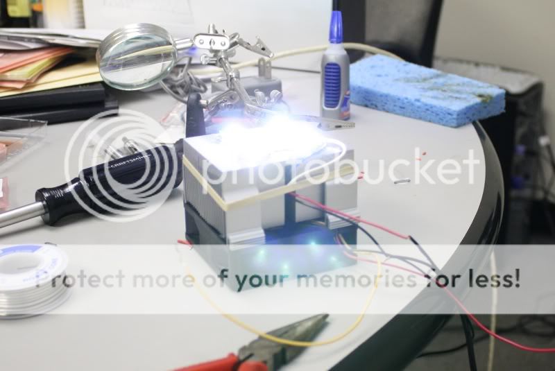
Now you will need to determine which is the positive wire coming from the power supply. Usually this is the one with the white strip running down the side of it. If you can not figure out which is positive don't worry, just pick one and if it doesn't work, switch them. Twist the positive (or what you think is positive) of the power supply with positive lead from the driver. Do the same with the negatives and then plug the power supply in. Be careful not to be looking at the LED's when they fire. You should have light.
If you don't have light, check all the connections. Make sure the LED's and driver are all properly connected. Mine didn't work at first because I had connected on of the LED's wrong. If all the connections are correct and it still does not work you probably have a bad LED, driver or power supply.
Once you have determined that you have a working light and that your connections are sound its time to permanently connect the power supply and the driver.
Get out your heat shrink tubing and locate two small ones and a large one. Slide the large one on the power supply wire and the two small ones over the individual positive and negative wires. Make the connections again and slide the small shrink tubes over them and shrink them with your heat gun or hair dryer. Then slide the large tube over the smaller ones and shrink that.
Conclusion
That's it! You're done! Well, pretty much done. Now you'll have to figure out a way to mount it and to keep saltwater away from the soldered connections which is not covered in this tutorial. I'll be mounting mine to the inside of my stand over the fuge with some paper providing a screen because when I see this thing operating, I get dots like from a camera flash.
Hopefully, after reading this tutorial and making a small, single string LED project, you will have gained the knowledge necessary to build a large scale LED fixture for a larger aquarium. Happy reefing!
:givebeer:
The purpose of this thread is to explain in detailed layman's terms the steps involved to make a simple LED light. You don't have to be an electrical engineer to make one of these lights. With a little effort, practice and some basic knowledge of electricity anyone can make an LED light fixture. This project is a good way for anyone with some reservations or hesitation about pulling the trigger on a large LED project to get their feet wet on something small so that they can get the basics down before diving into something major. I am by no means an expert on electricity and this is only my second time soldering anything. I'm planning on doing a large scale fixture for my 75 gallon in the future.
Step 1: Gathering supplies
Tools -
Soldering iron ? get a good one from weller, I did not do this and I am paying for it now! This one I am using is terrible.
Sponge
needle nose pliers
toothpicks or paperclips
screwdriver ? I needed this, you may or may not
heat gun or hair dryer (cigarette lighter will work in a pinch)
Materials -
First a little background on how LEDS are typically configured for an aquarium as this will help you to understand how to pick your materials. Most people are using a DC power supply of some kind and connecting a number of drivers to that and then connecting strings of LED's in series which means connecting the negative of one to the positive of the next in a 'string'. The amperage of the power supply will tell you how many strings you can run and the voltage will tell you how many LED's it can power on each string. I suggest you click the links in the below sections to gain a better idea of what I am explaining as they are mostly to data sheets which are important and you will be referring to them when planning to do a larger project.
LED ? The LEDS you choose will be based on your project. I chose 4 white Cree XPE from dealextreme for mine as I wont be needing blue because this will be a fuge light. The data sheets for these LED's can be found at Cree's website. Choose Your LED's carefully as they are not all extremely bright like these. Look for the correct bin. You'll want the 'luminous or radiant flux group' section of the bin to say Q4 or Q5 for white. The royal blue color is great for actinic and makes coral color pop. You'll want your LED's to come pre-mounted because when they are unmounted they are very small and impossibly hard to solder for a novice. Here are some good websites to buy the kind of LED's and supplies we will be needing.
http://www.ledsupply.com/
http://www.dealextreme.com/
http://www.cutter.com.au/
Driver ? You need a constant current driver to run these LEDs. I don't want to get into all the reasons why you need this, just know that if you try to not use a driver your LEDS will not last very long. For this project I chose to use a regular non-dimming 1A Luxeon buckpuck from ledsupply. There are for clearly labeled wires coming out of it, two (+ and -) connect to the power supply and two (+ and -) connect to the LED string.
Power Supply ? For this small project look for one of those big black square plugs that most all of your electronics uses. I chose one that was for a cable modem. Look at the label of your power supply. The amperage will tell you how many strings of LED you can run from it and the voltage will tell you how many LEDs it can power on each string. Just add up the voltage of all the LED's which run at 3.7V each. Since my buckpuck is 1A and must have an input voltage between 5-32 V my 1A 15V DC power source should work fine for 1 string of LED running at 1A and since the forward voltage of each LED is 3.7V I can power a max of 4 LEDs on the string because the fifth would put me over 15V. For larger projects, get bigger power supplies (like for computers) which generally can do 24V and more amps lets say for example 8A, which would allow you to run 8 strings at 1A and 6 LED per string for a total of 48 LED .
Heat sink ? You will be needing a heat sink of some kind. This is what you mount the LED's to. These kinds of LED get very hot and can damage themselves if they get too hot. Copper or aluminum work great for this. A small piece of aluminum will work fine (can be found at home depot). I chose a processor heatsink and fan because I already had it in a pile of computer junk. For a project this small it really doesn't matter what you choose so long as there is something there dissipating the heat. For larger projects, the heatsink becomes much more crucial. You should also give some thought to how you will be mounting the heat sink over the tank and possibly how you will be shielding it from saltwater. These concepts are not covered in this tutorial.
Other materials -
Arctic silver thermal epoxy ? I chose to use this as it is the easiest method of mounting the LED's while and is made for heat transferring situations like this.
60/40 rosin core solder ? the appropriate solder for the job
22awg solid copper wire ? thin and easy to work with. Any thin wire works though, I used speaker wire on my first led project.
Heat-shrink tubing ? for insulating wire connections
Step 2: Mounting the LED's and driver
First make sure your heat sink is clean and has ample space to mount your LEDs. Mine had this copper bar on the bottom and under it was a bunch of thermal paste that I had to clean off with some tissue paper.
Decide how you want to arrange the LED's. Take note of where the + and ? soldering pads are on the stars because we will be soldering small bits of wire to these to connect the LED's in a string.
There are usually two +'s and two -'s on each star. Either will work fine and you will not use all the pads.
Take into account that you will be connecting the positive lead from the driver to the positive on the first LED. Then you connect the negative from that first LED to the positive of the next one and so on until they are all connected with the negative of the last LED connected to the negative lead from the driver so to make it easy, try to make the pads line up.
Pick an out-of-the-way spot for your driver such as the back or side of your heat sink. These heat up a bit as well so you can use the thermal epoxy to glue it. Just make sure the wires can reach what you have chosen as your first and last LED. Superglue does not work.
Take your time with this step and plan out what you are connecting and where. You want the pads to be close but don't put them so close that it is difficult to bridge the connections with a small bit of wire.
The Arctic silver thermal epoxy is a two part epoxy. Mix up equal parts of it on a paper plate or some paper using the toothpicks or paper clips. You'll only need a tiny glob of each. I made one of my gobs too big and then had to add more of the other part and ended up with a lot of waste.
After mixing, put a small amount where you want the LED to attach and press down a little. You only need a tiny amount of epoxy to attach them. I actually tried to remove one and that was definitely a no-go. This stuff is very strong so take your time and make sure you do it right the first time.
Attach all the LED's and drivers this way to your heat sink of choice. Let the glue set for about 5 minutes before soldering to the stars.
Step 3: Preparing the wires
Steps 3 and 4 are going to be repeated until you have the entire string connected. Do step 3 (Measure, strip, tin) then step 4 for each connection you have to make. Do not cut all the wires and then tin and connect them because you will confuse yourself, just do one connection at a time.
Plug your soldering iron in so that it starts heating up we will be using it for the next few steps. Also, wet the sponge (not sopping wet, just dampen it) we will be needing that as well.
Measure the wire and cut it. Do not use more wire than you need. It is best to make the wires as short as possible.
Strip off some of the insulation. Do not strip off more than you need to. You see these tiny little pads on the LED stars? You will only need bare wire of about the width of one of those pads. Use your dykes or needle nose pliers to accomplish this. Just squeeze the cutting blades of your tool down a bit and release repeatedly while rotating the piece of the wire. This will score the insulation which you should be able to tear off with your thumbnail.
Disclaimer: I am an extreme novice at soldering and barely have the skills to do this project. I know there are ways to get the solder much much neater but that is not our goal here. This tutorial is written by someone who knows only the basics of soldering and for people with no experience doing it. Also, THE SOLDERING IRON IS VERY HOT DO NOT TOUCH IT OR PUT IT DOWN ON ANYTHING THAT CAN BURN BECAUSE IT WILL BURN IT!!!:lol:
Now, we will be 'tinning' the wires which is basically just getting some solder on the bare tips we've made. This is how I did it, look here to find the correct way. To do this pick up your (hopefully hot by now) soldering iron and touch the solder to it. You will see the solder melt instantly and appear to become part of the tip, its not. Quickly rub the tip on you sponge and you should see the solder get shiny and start to look something like the T-1000 from terminator 2 (liquid metal). Then apply this to the tip of the wire by touching it to the bare end of the wire. MAKE SURE YOU HOLD THE WIRE WITH THE TWEEZERS OR NEEDLE NOSE PLIERS BECAUSE THE IRON IS INCREDIBLY HOT. You should only need a tiny bit of solder on the tip of the wire, just enough to turn the exposed copper silver in color, if you get more than you need on the tip, no big deal. Touch the iron to it briefly and some should stick to the iron. I'm sorry i don't have better pictures of this but I don't feel comfortable handling the camera and the soldering iron at the same time so this one will have to do.
Step 4: Making the connections
Now we will be connecting the LED's. First get some solder on your iron like we did for tinning the wires (apply solder and wipe on sponge). Then touch the iron with solder onto one of the pads so that you get a little gob of solder on it. Do this again for the other pad you are connecting with.
Pick up your tinned wire from last step with tweezers or needle nose pliers. Hold the wire in place with the ends touching the two pads that you are connecting (with the pre-applied gobs of solder) and touch the iron to it. Be careful not to touch the iron to the LED itself because that will ruin it. You should only need to keep the iron there for a split second to melt the solder. You can then release the wire and make the other connection the same way, just briefly touch the iron to the solder and the tinned wire to connect them.
That wasn't so hard, was it? Now repeat steps 3 and 4 until you have connected all the LED's, negative to positive, unlike the above picture. can you spot the error? :tub:
Tin the ends of LED leads from the driver and connect the positive lead to the positive of your first LED and negative to the negative of your last LED.
I figured out during the next step that I had made some connections wrong.:iamwithst
Step 5: preparing and connecting the power supply
Your power supply probably has one of these round proprietary connectors on the end of the wire that connects to whatever it was meat for. Just go ahead and cut that connector right off.
Divide the wire down the center and strip about ? to ? of an inch of the insulation off just like we did before. Be careful though, the wires are probably stranded, which means instead of a a single wire inside the insulation, there will be a number of thinner wires inside there. This is to make the wire more flexible. After stripping the insulation off, twist the bare wire together.
Now you will need to determine which is the positive wire coming from the power supply. Usually this is the one with the white strip running down the side of it. If you can not figure out which is positive don't worry, just pick one and if it doesn't work, switch them. Twist the positive (or what you think is positive) of the power supply with positive lead from the driver. Do the same with the negatives and then plug the power supply in. Be careful not to be looking at the LED's when they fire. You should have light.
If you don't have light, check all the connections. Make sure the LED's and driver are all properly connected. Mine didn't work at first because I had connected on of the LED's wrong. If all the connections are correct and it still does not work you probably have a bad LED, driver or power supply.
Once you have determined that you have a working light and that your connections are sound its time to permanently connect the power supply and the driver.
Get out your heat shrink tubing and locate two small ones and a large one. Slide the large one on the power supply wire and the two small ones over the individual positive and negative wires. Make the connections again and slide the small shrink tubes over them and shrink them with your heat gun or hair dryer. Then slide the large tube over the smaller ones and shrink that.
Conclusion
That's it! You're done! Well, pretty much done. Now you'll have to figure out a way to mount it and to keep saltwater away from the soldered connections which is not covered in this tutorial. I'll be mounting mine to the inside of my stand over the fuge with some paper providing a screen because when I see this thing operating, I get dots like from a camera flash.
Hopefully, after reading this tutorial and making a small, single string LED project, you will have gained the knowledge necessary to build a large scale LED fixture for a larger aquarium. Happy reefing!
:givebeer:
")