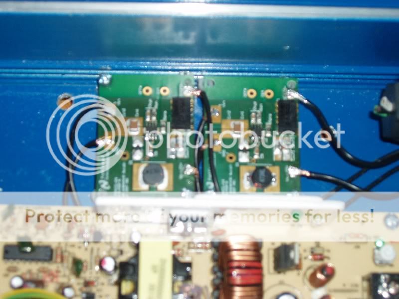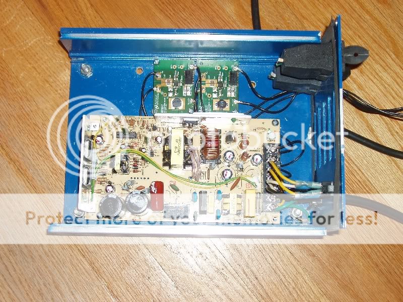

Just wanted to share my project so far that I have been working on. The main concept behind this fixture was to desgin a driver cricuit that will be able to dim using PWM(pulse width modulation). I designed the 2 circuits 1 for each color using the LM3404 regulator IC. These circuits have an at effiency rating of about 96%. The blue LEDs are running at 700ma and the Whites are running at 800ma. I just used a regular 24v/6 amp switching power supply. Its not the best since it has a ripple voltage of 240mV but it does the job. I only used 12 LEDS here just to keep it simple although it is extremly bright and has about 1800 lumens from my calculations. I have no idea as to how much PAR it is giving out but I thought this was pretty amamzing considering im only using about 30 watts of total power. I had the boards made for me using the GERBER file from National semiconductors evaluation board. I plan to use the Atmega318 Microcontroller board with the ds1337 RTC for programming. So far I just have some simple PWM program that shows the dimming affect. As you can see it has a coincell in there so it doesnt lose the time after the power is cut. Im still working on the full program and planning to integrate a touch LCD screen. I just mounted this in an old Sunlight supply ballast housing which turned out very nice. Just looking to get some feedback. If these is interest in the driver boards they can be made for under 25 bucks much less than any others on the market today.